STS essentials
A Static Transfer Switch, or STS as it is commonly referred to, can be defined as an AC/AC solid-state converter. It supplies the output with one of two input lines where the AC/AC conversion is performed by a pair of Silicon Controlled Rectifiers (or SCRs). Functionally an STS implements a Single Pole Dual Throw switch of a static kind, as opposed to an Automatic Transfer Switch (ATS), where the switches are electro-mechanical.
Besides inherently higher reliability due to the use of solid-state components as opposed to electro-mechanical ones, the main difference between STSs and ATSs is a shorter transfer time: 2-3 ms against 100 ms or more. Therefore, while less expensive ATSs are commonly used as the source changeover, i.e. between commercial utilities and generator sets, STSs are the only option to seamlessly transfer power between power feeds downstream of the UPS system.
STS Ampere rating
Like electro-mechanical switches, STS are current rated systems. The main defining figure is how many Amperes they can indefinitely let flow and switch. Although STSs also have a voltage rating, which is related to the components’ safe operating area, power ratings do not apply and therefore no kVA figure should be used in defining STS requirements.
3 and 4 pole STS
A three-phase STS can be 3- or poles, meaning that the system is featuring three or four wires for each of the two input lines and the output line. The fourth being the neutral wire. 3- pole STSs are used in pure three-phase arrangement, where the neutral wire is not used at all, or when the two sources feeding the STS share a common neutral and there is no need to switch or disconnect it.
On the other hand, four pole STSs must be used whenever a neutral disconnection is required. Four pole STSs can further be divided in two categories: switched or non-switched neutral, meaning that the neutral wire is equipped or not with the relevant SCR pair.
As far as two 4-wire independent sources are concerned, 4-switched-pole arrangement should be used, in order to prevent the two independent neutrals to be connected together, which is the case whenever a 4-non-switched-pole STS operates normally, with both its 4-pole input switches closed. As an example, an STS basic requirement should read as: 630 A, 400 V, 4-switched poles.
STS in data centres
Despite STSs being general purpose equipment, they are far more popular within data centres (DC) than in any other industry. The reason being is the massive deployment of redundant schemes that the DC market has experienced over the past decade. In addition to the typical A-B dual supply, different redundancy schemes have been more recently developed following the constant trend for both cost and carbon footprint reduction. Distributed redundancy 3 out of 4 and failover schemes to name a few, have therefore become more and more popular due to the benefit of a lower UPS power deployment.
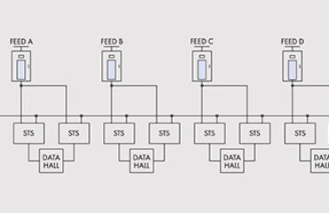
In the distributed redundancy 3 out of 4 arrangement, ’1.5N’ UPS power is required, where ‘N’ is the total IT required power, against the most resilient, but quite expensive ‘2N’ scheme. Even less power is deployed in the failover arrangement, that is equivalent to a proper ‘N+1’ scheme, where one UPS acts as the backup power source for a set of same size UPS units feeding an overall ‘N’ design. In both schemes STS units are required to distribute the UPS power to the IT loads, as to maximize availability.
Single phase STSs are widely used at PDU level, that is in the power section of the racks, to provide both feeds of a redundant arrangement to non-dual SMPS (Switch Mode Power Supply) servers or network equipment. In this application, SCR-based STSs are usually preferred as opposed to relay-based units, due to the former’s superior switching performance and durability.
For more information on Borri 1-phase and 3-phase STSs please download our brochure or visit our STS 16-32 and STS 300 web pages.
For further inquiries you can email us at info@borri.it


 Global
  Italiano
  Русский

